Background
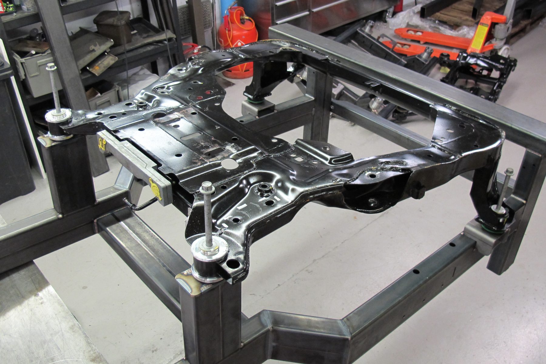
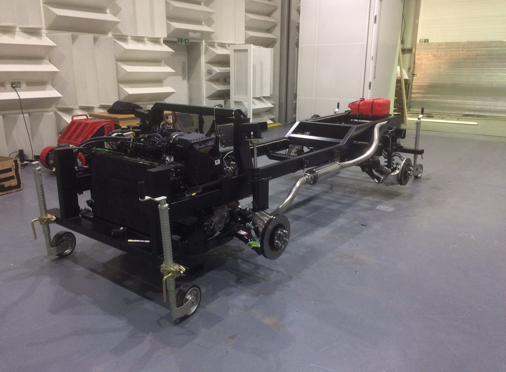
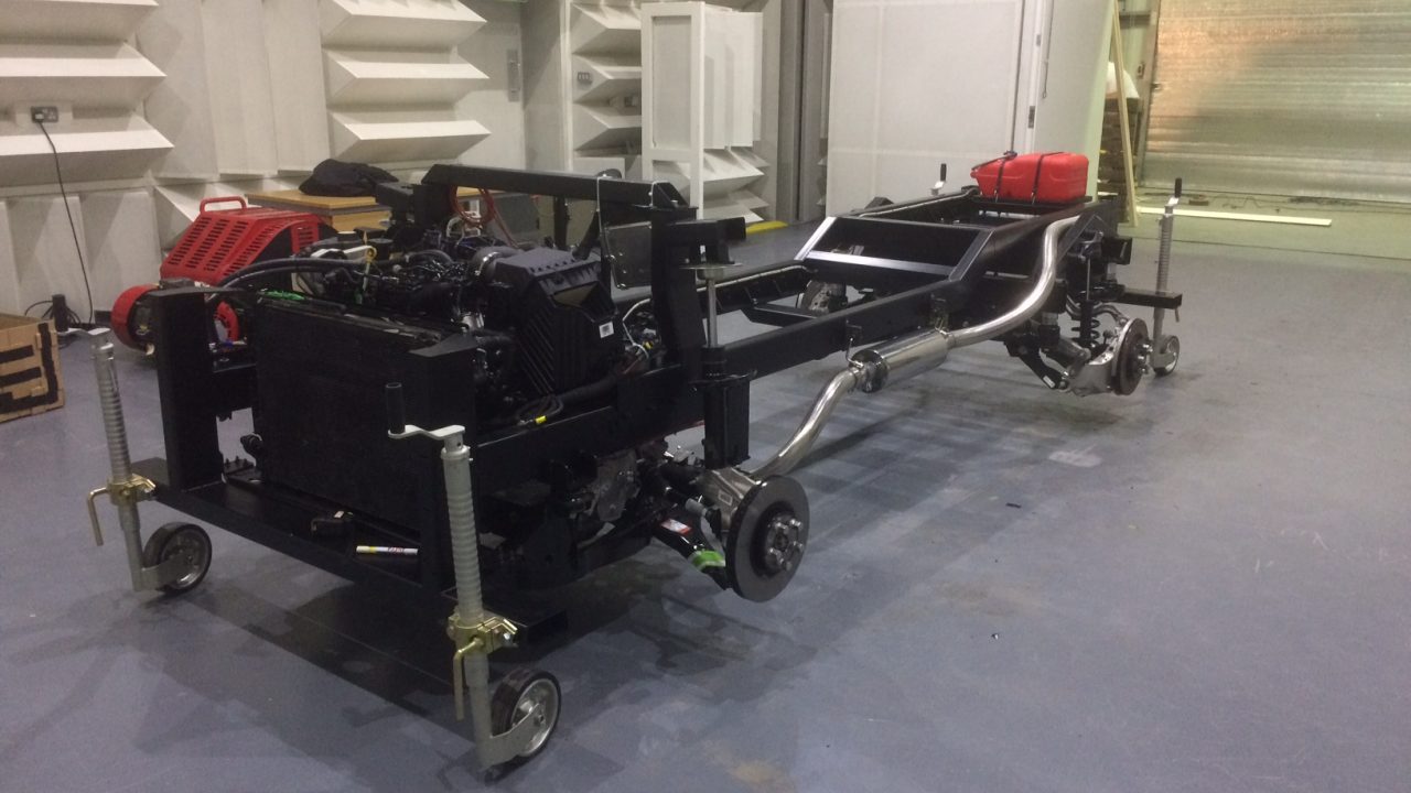
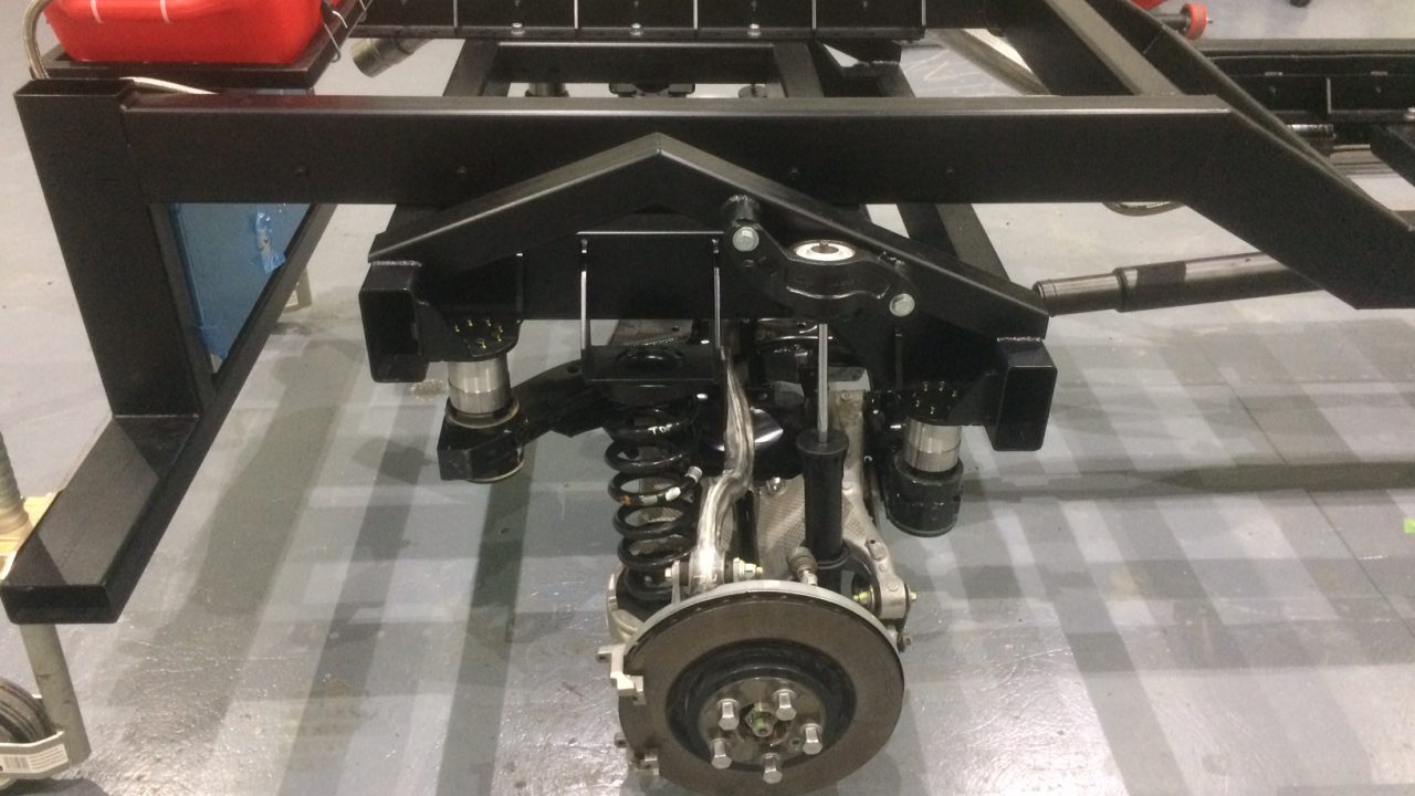
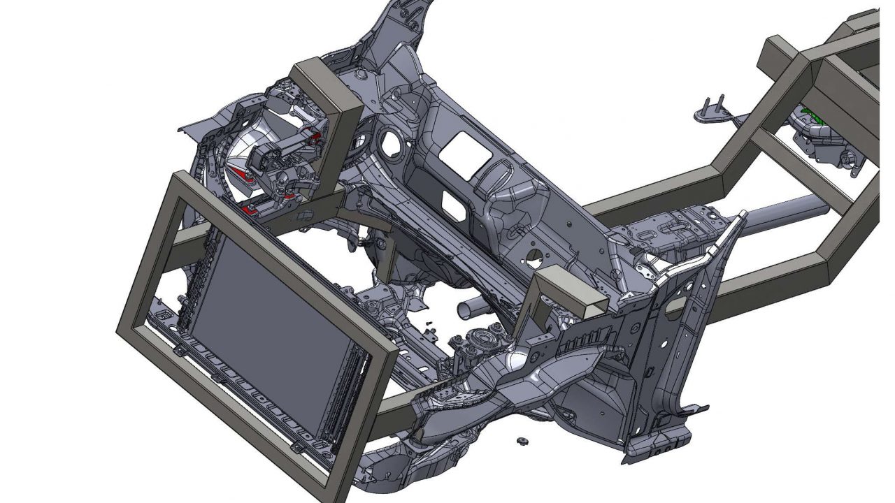
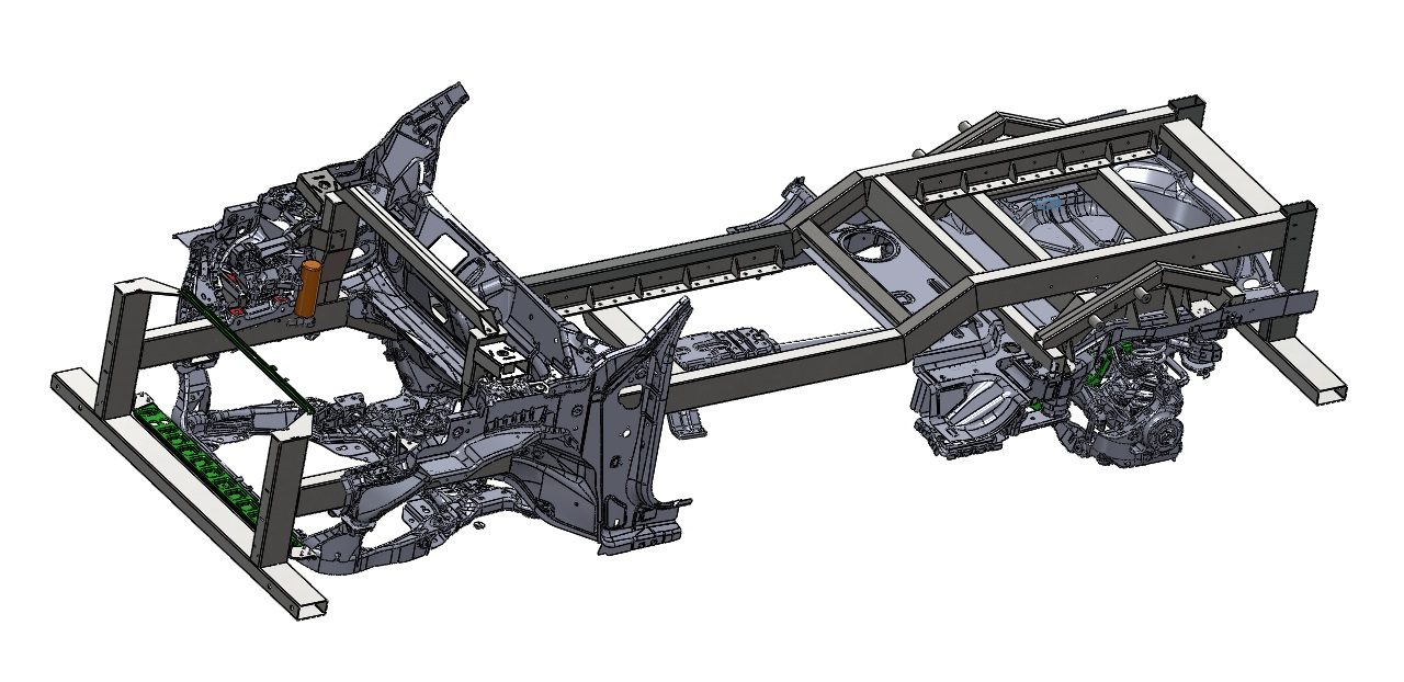
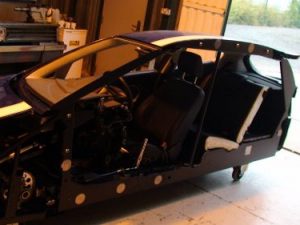
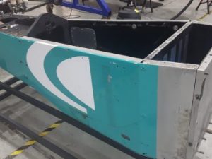
Customer required a robust chassis structure to accept all standard running gear parts from a road vehicle for static testing of parts whilst vehicle was running / driving.
General spec included
- Both front & rear crossmembers
- Both front & rear suspension assemblies
- Engine / gearbox assy
- Propshafts & bearing mounts
- Front & rear axles / driveshafts / hubs
- Radiator / cooling pack
CAD import process
Process
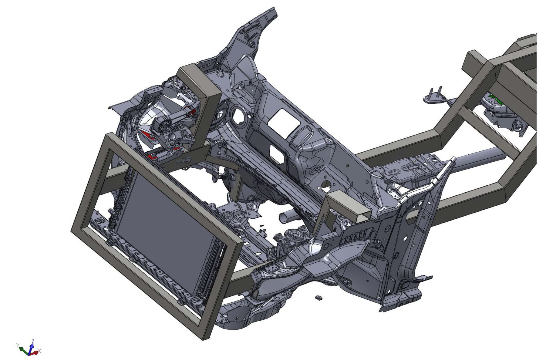
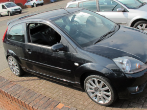
The Customer provided 3D CAD information for the existing road car chassis.
Using specialist translation software we converted all the CAD information into a file format suitable for Solidworks and created a new assembly model of the original vehicle chassis.
Design Process
Process
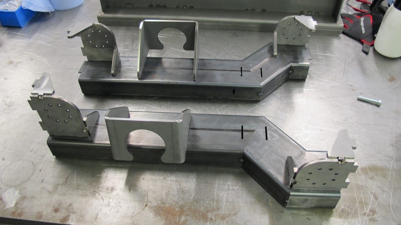
Using the original chassis CAD a new chassis was designed incorporating all original mount points and new load cells in critical areas.
Once the design was completed and approved, drawings were done for all new tube, sheet and machined parts.
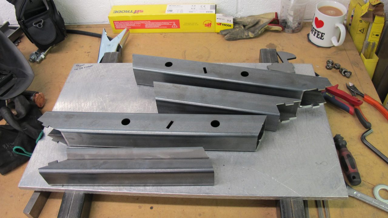
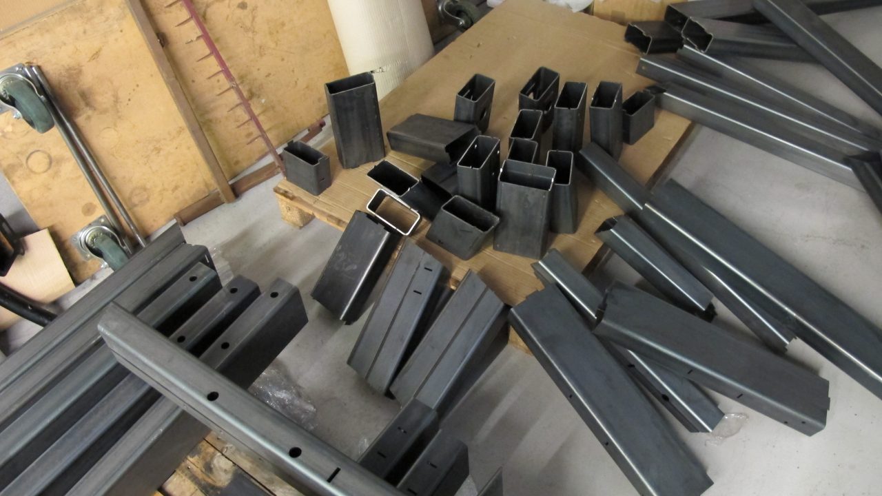
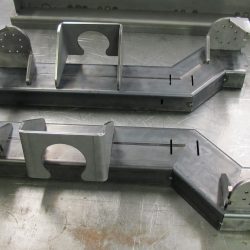
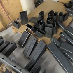
All tube and sheet parts were laser cut.
Assembly and manufacture
Process
- All tube and sheet laser cut and bent by sub-contract suppliers and supplied to us ready to assemble /weld.
- The tube and sheet parts were assembled using pegs and slots – no jigs or fixtures were required.
- All parts fully TIG welded
- Chassis painted by sub-contractor supplier
- Chassis supplied to customer painted, and loosely assembled with crossmembers
Approximate time of completion – 8 weeks
